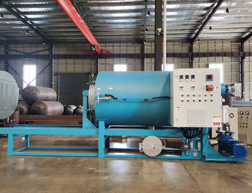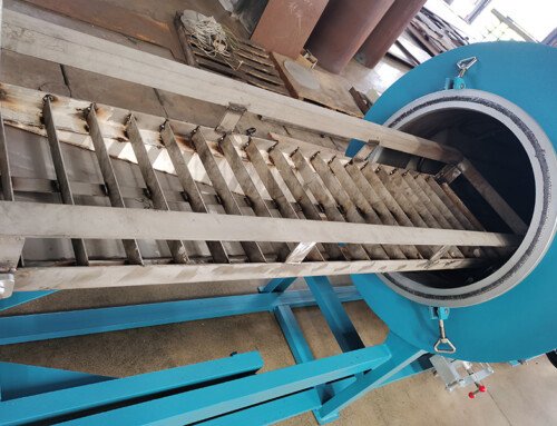
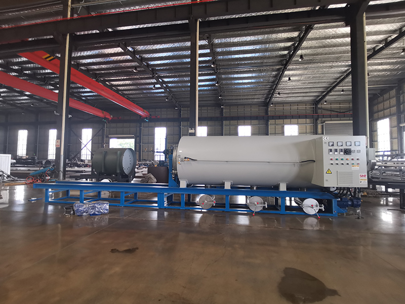
Start with the most accessible checks that do not require opening any internal panels. Walk over to the main control interface and observe whether the current displayed time matches the actual local time. Many timing failures trace back to a drifted clock after a recent power interruption, which shifts all pre-programmed start and stop points out of alignment.
Check the physical lock setting on the control panel next. Some units include a multi-level screen lock that restricts access to timing adjustment menus even when other basic functions remain active. If the interface does not respond when you press keys to edit scheduled cycles, cycle through the lock options to confirm full access to timing parameters is enabled. You should also verify that the selected operating mode supports timed runs, as certain manual or diagnostic modes will bypass all scheduled events by design.
Wiring and Sensor Input Verification
Move to the low-voltage terminal block behind the control panel once basic interface checks return no issues. Inspect the two wires that carry real-time clock power and timing trigger signals, looking for loose crimps, faint corrosion on exposed copper, or traces of heat discoloration near the connection points. A slightly loose wire can deliver enough power to keep the basic clock running but drop voltage the moment the timing circuit tries to send a start signal to the main heater.
Trace the external run confirmation sensor line that feeds status data back to the timing board. If this sensor is coated in fine residual dust from regular operation, it may send a false “already running” signal that tells the timer to skip the scheduled cycle entirely. Wipe the sensor surface gently with a dry lint-free cloth, then run a single manual cycle to confirm the sensor can detect normal operation before reactivating the timed schedule.
Internal Timer Board Diagnostic Steps
Remove the board from its mounting bracket after disconnecting main power, and inspect the surface for swollen capacitors, faint burn marks near the timing crystal, or cracked solder joints around the integrated circuit that stores schedule data. These small components degrade slowly after thousands of heating cycles, and they often cause intermittent timing faults that appear only after the unit warms up to operating temperature.
Locate the small reset pin on the timer board, press and hold it for 45 seconds, then re-enter the full 7-day timing schedule from scratch. Do not simply reuse the old saved schedule, as corrupted memory bits can continue to trigger skipped events even after a basic power cycle. Document every programmed start time and duration on a notepad before testing, so you can cross-reference exactly which scheduled event fails to trigger during the next full operating cycle.
Intermittent Fault Pattern Tracking
Run the unit through three consecutive full timed cycles and note the exact time any failure occurs. Pay attention to whether the fault only appears when the ambient workshop temperature drops below a certain threshold, or if it happens immediately after the exhaust fan activates at the end of a cleaning run. Many hidden timing faults only show up under specific thermal or electrical load conditions that do not appear during a quick bench test.
Check the auxiliary power line that supplies power to the timer circuit while the main heating element is active. If voltage dips below the manufacturer’s specified threshold for more than two seconds during a heat-up phase, the real-time clock can reset its internal count without losing the displayed time on the screen. This creates a silent offset where the timer thinks it is still waiting for a scheduled event that should have already triggered minutes earlier.