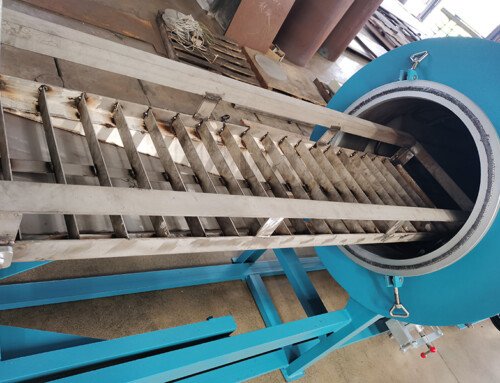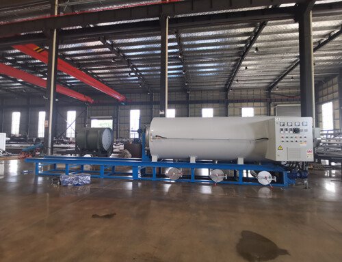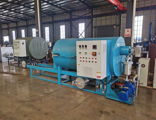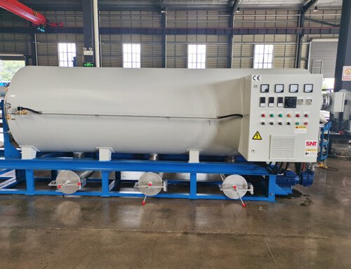
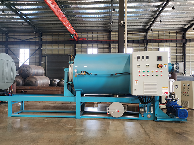
The sudden or planned shutdown of a screw cleaning furnace due to a fault presents a significant operational hazard if not managed with a strict, methodical safety protocol. Unlike routine stoppages, a fault condition—whether triggered by a thermal runaway, pressure anomaly, mechanical seizure, or control system failure—introduces uncontrolled variables. A structured safety response is essential to protect personnel, prevent equipment damage, and secure the process area from the risks of residual heat, trapped pressure, or the release of unreacted cleaning media. This process transitions the system from an unstable fault state to a controlled, safe, and isolated condition, forming the critical bridge between incident response and subsequent diagnostic repair.
Immediate Response and Process Isolation
The first moments following a fault alarm are decisive. The primary objective is to halt the active cleaning process and isolate energy sources to prevent the fault from escalating. Operators must first acknowledge the alarm on the Human-Machine Interface (HMI) or control panel to silence audible alerts and clearly identify the fault code or description. Without delay, the primary process stop must be executed. This involves engaging the main emergency stop (E-stop) circuit, which is designed to simultaneously cut power to the screw drive motor, heating elements, and any auxiliary pumps or conveyors. This action is non-negotiable and overrides any automated control sequences.
Following the E-stop, systematic energy isolation begins. This is a lockout-tagout (LOTO) procedure. All energy sources feeding the furnace must be physically disconnected and secured. This includes:
- Electrical Isolation: Locating and switching the main power disconnect for the furnace control cabinet to the “OFF” position. Each operator involved must apply their personal safety lock and tag to the disconnect.
- Thermal Energy Management: Recognizing that the screw, barrel, and heating jackets will retain substantial heat. The procedure must account for this stored energy by prohibiting contact and posting clear “HOT SURFACE” warnings around the equipment.
- Pressure and Chemical Isolation: Closing manual block valves on all process fluid lines (e.g., cleaning solvent supply, coolant lines, pneumatic air) to prevent any unintended release or flow. If the furnace uses a closed-loop solvent system, particular attention is paid to isolating pumps and securing vessel vents.
System Depressurization and Atmospheric Stabilization
With the system isolated, the next priority is to safely vent any trapped pressure and purge hazardous atmospheres. A screw cleaning furnace operating under fault conditions may contain pressurized gases from solvent vaporization or thermal decomposition. Attempting to open any inspection port, door, or drain valve before confirming a safe internal pressure is extremely dangerous.
The safe pressure equalization sequence involves consulting the system’s piping and instrumentation diagram (P&ID) to identify the designated safe vent line, which is typically routed to an extraction system or safe outdoor location. Operators slowly open the manual vent valve in short increments, listening for the sound of gas flow and monitoring any connected pressure gauges. This is done cautiously to avoid a rapid pressure drop that could cause violent movement of internal components or create a vacuum. The goal is to gradually bring the internal pressure down to ambient atmospheric pressure.
Concurrently, atmosphere control is addressed. Many cleaning processes use flammable or toxic solvents. Before any physical entry or close inspection, the internal atmosphere must be verified as safe. This is achieved by:
- Initiating a purge cycle using an inert gas like nitrogen, if the system is so equipped, to displace oxygen and solvent vapors.
- Using a calibrated, intrinsically safe multi-gas detector to sample the atmosphere at various access points. Readings for Lower Explosive Limit (LEL), oxygen deficiency, and toxic gas levels (like CO or solvent vapors) must all be within safe thresholds before proceeding.
- Ensuring the facility’s local exhaust ventilation (LEV) at the furnace doors and ports is activated and functioning to maintain a safe breathing zone for personnel during subsequent steps.
Secure Lockout and Post-Isolation Verification
The final phase establishes a verifiably safe work condition for maintenance technicians. Comprehensive lockout extends beyond the main electrical disconnect. Technicians must identify and lock out all potential energy sources, including secondary control circuits, backup power systems, and stored mechanical energy in components like gas spring-assisted doors or counterweights. Each energy isolation point receives a tag clearly stating the reason for lockout and the name of the person who applied the lock.
A critical and often formalized step is the verification of zero energy state. Before any hands-on work begins, a qualified person performs a “try-out” test. This involves attempting to start the equipment using the normal operating controls (e.g., pressing the start button) after the isolation is complete. The verification is successful only if the equipment does not respond in any way—no movement, no activation of lights or indicators tied to primary power, and no sound from motors or solenoids. This test provides positive confirmation that all hazardous energy has been effectively isolated.
Only after passing this verification can the physical access and assessment begin. Technicians can now safely open inspection hatches, use thermal imaging cameras to identify hot spots, and visually inspect the screw, barrel, and internal components to begin diagnosing the root cause of the initial fault. The entire area remains cordoned off, and all personnel involved must have completed specific training on this equipment’s lockout/tagout procedures. This meticulous, step-by-step approach ensures that the response to a fault prioritizes human safety above all else, creating a stable platform for effective troubleshooting and repair.