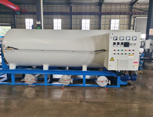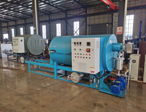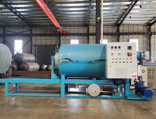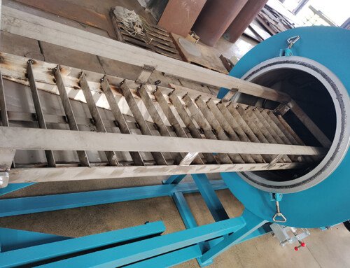
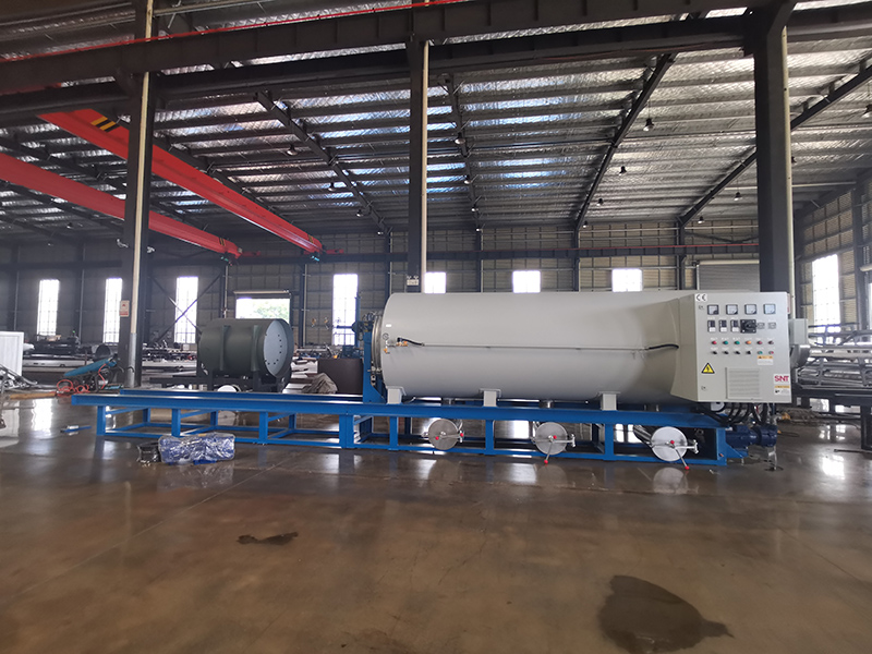
Screw cleaning furnace proper on-site placement rules define the safe, efficient structural framework for positioning this high-temperature industrial equipment within a factory layout, ensuring stable long-term operation, easy routine maintenance, and full compliance with on-site fire safety and ventilation standards. A well-planned placement arrangement eliminates hidden operational risks that can emerge over months of continuous use, while also reducing unnecessary handling steps for teams moving heavy workpieces in and out of the unit. Every decision follows practical industrial site experience, rather than generic equipment guidelines, to fit the unique workflow patterns of a typical processing plant environment.
Clearance and Workflow Channel Planning
The first core principle focuses on building unobstructed movement space around the unit that supports smooth, unimpeded material handling and daily operational tasks. A dedicated primary access zone is reserved on the side where operators load and unload screw workpieces, with enough room to maneuver lifting aids and transport carts without bumping into adjacent equipment or stacked inventory. A separate narrower maintenance channel is kept completely clear on the opposite side, giving technicians full access to rear wiring assemblies, ventilation components, and internal inspection points without needing to squeeze past obstacles or temporarily move unrelated equipment. The layout also leaves extra empty space near the unit’s ash discharge and waste collection area, so teams can safely remove residual material without spilling debris onto main walkways or creating tripping hazards for passing personnel. This structured channel division prevents workflow conflicts between operators, maintenance staff, and other teams moving through the surrounding factory zone.
Thermal Environment and Heat Dissipation Layout
Placement must account for consistent ambient temperature control to avoid uneven heat buildup that can strain the unit’s heating system and shorten component lifespan. The unit is positioned far away from other high-temperature heat sources that could raise local ambient temperature above normal working limits, preventing overlapping thermal radiation that creates unplanned local hot spots around the furnace body. At least two sides of the unit are kept fully exposed to circulating factory air flow, with no large enclosed partitions or stacked tall materials blocking natural heat dissipation paths. The layout also avoids low-lying areas where heavy, stagnant hot exhaust could accumulate, and instead aligns the unit’s main ventilation outlet toward the factory’s general exhaust direction to carry residual fumes and waste heat quickly out of the working zone. This careful thermal positioning keeps the unit’s external surface temperature stable, reduces unnecessary load on internal temperature control systems, and prevents stray radiant heat from damaging nearby sensitive equipment or stored materials.
Ground Load Bearing and Anti-Vibration Positioning
The selected placement location must meet strict ground load bearing requirements that can safely support the full weight of the unit when it is fully loaded with heavy workpieces and operating at maximum high-temperature state. The ground surface beneath and around the unit must be completely flat, solid, and free of cracks, uneven patches, or soft spots that could cause subtle structural tilt over long-term operation. The zone is also positioned outside the main vibration path of nearby heavy industrial machinery, to prevent continuous low-frequency vibration from loosening internal wiring connections, disrupting temperature sensor calibration, or creating unnecessary stress on high-temperature sealing components. No dynamic impact operations such as heavy forging or metal cutting are allowed to be set up within the immediate surrounding area, creating a stable, low-disturbance base environment that supports consistent, reliable furnace performance across thousands of operating cycles.
Safety Buffer and Peripheral Protection Arrangement
A dedicated safety buffer zone is marked around the entire perimeter of the unit, clearly separated from general employee walk paths and unrelated working areas to prevent accidental contact with high-temperature external surfaces during operation. No flammable materials, chemical storage containers, or scattered dry processing debris are allowed to be placed inside this buffer zone, eliminating hidden fire risks that could be triggered by stray radiant heat or accidental hot material spillage. The unit is also positioned within easy line of sight of the factory’s main fire safety equipment, and within short walking distance of fixed emergency power cut-off points that can quickly shut down all power to the unit in case of unexpected operational anomalies. This final layer of placement planning ensures that even in rare unplanned scenarios, on-site teams can respond quickly and safely without navigating around obstacles or traveling long distances to reach critical safety controls.