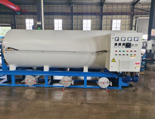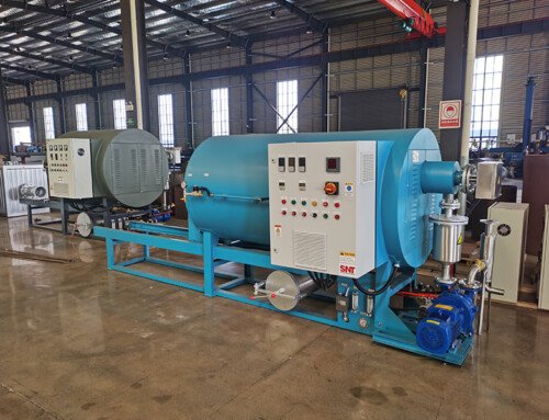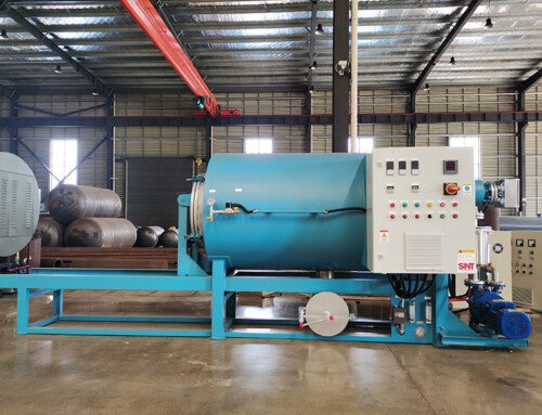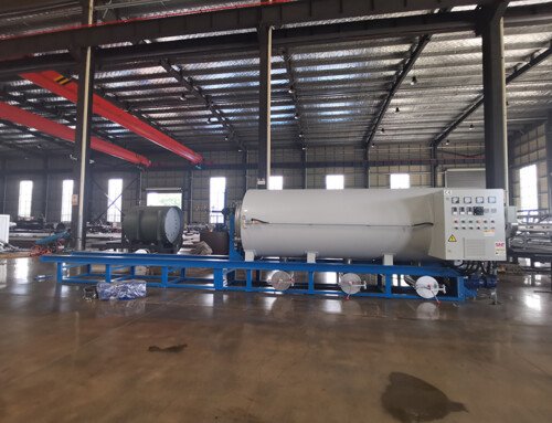
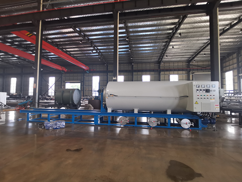
A well-planned workshop layout for the screw cleaning furnace balances operational flow, safety clearance, structural vibration control, and long-term maintenance accessibility. Poor placement can create unnecessary workflow bottlenecks, expose operators to avoidable thermal hazards, and even amplify structural vibration that gradually undermines equipment stability. The following practical considerations focus on spatial logic, environmental compatibility, and day-to-day usability to support smooth, consistent operation across extended production cycles.
Workflow alignment and material movement routing
Map the full sequence of material transfer before marking any fixed position on the workshop floor. Position the unit along the natural flow path that leads from pre-treatment preparation, through the cleaning cycle, and onward to post-processing handling, so operators do not need to carry heavy loads across long distances or cross high-traffic aisles repeatedly. Avoid placing it in a dead-end corner that forces incoming and outgoing material streams to reverse direction, as this creates unnecessary congestion and increases collision risks with passing carts.
Reserve dedicated temporary staging space on both the inlet and outlet sides. This area should hold enough space for waiting batches and cleaned components without blocking emergency exits or shared walkways. Make sure the layout keeps raw material zones, the equipment operating zone, and finished component storage clearly separated, so cross-contamination from debris or residual processing material stays under control.
Structural load and vibration interference prevention
Place the unit on a floor section with sufficient structural load capacity, ideally on the ground floor rather than on an upper mezzanine unless the building’s structural calculations explicitly support the weight and dynamic forces involved. Avoid positioning it directly above building expansion joints, utility trenches, or sections of the floor with known structural weaknesses. This prevents uneven settlement and reduces the chance of amplified vibration transferring through the floor slab.
Keep a safe clearance zone between the unit and other high-vibration equipment nearby. This separation prevents periodic vibration from neighboring machinery from coupling with the furnace’s own operating frequency and triggering unexpected resonance. If the workshop layout is compact, add extra structural reinforcement or dedicated isolation zones between adjacent high-force equipment to break any potential vibration transmission path.
Thermal environment and surrounding clearance planning
Leave sufficient open space around all sides of the unit to support natural heat dissipation. Do not position it directly against a poorly ventilated wall or stack flammable consumables within the recommended safety distance from high-temperature sections. Maintain unobstructed airflow paths around the outer shell, so ambient heat does not accumulate and raise local workshop temperature beyond comfortable working limits.
Arrange the layout so operators face away from direct glare from large windows when standing at the main control position. This reduces visual fatigue during long shifts and makes digital readouts and status indicators much easier to read accurately. Keep tall storage racks and other large obstacles from blocking natural ventilation openings near the equipment, as trapped hot air can shorten the service life of nearby electrical components.
Maintenance access and safety zone reservation
Reserve a full clear access path that leads directly to every major service point on the unit. This includes areas for heating element inspection, internal screw path cleaning, drive system servicing, and routine component replacement. No fixed workbench, storage bin, or temporary material stack should block these access routes, so maintenance teams can complete inspections and repairs quickly without moving heavy obstacles out of the way first.
Designate a clear safety perimeter around the equipment that stays free of tripping hazards, loose cables, and scattered debris. This zone gives operators enough room to respond immediately if an unexpected operational issue arises, without stepping over obstacles or bumping into nearby objects. Mark this implicit boundary through consistent workshop layout planning rather than relying on temporary warning signs that can be moved or ignored over time.
Utility connection routing and spatial coordination
Route all required utility lines along pre-planned dedicated paths that do not cross main walkways or material transfer routes. Keep power connections, ventilation ducts, and process supply lines organized so they do not hang loosely or create hidden collision points above the working area. Avoid running utility lines directly over the top of high-temperature sections, to prevent unnecessary long-term thermal exposure that could accelerate material aging.
Coordinate the layout with other nearby fixed equipment to make shared utility points as efficient as possible. This reduces unnecessary long-distance piping and cabling runs that create extra clutter and make later troubleshooting much harder. Every connection point should remain easily reachable for routine inspection, without requiring operators to stretch across hot surfaces or climb over unguarded structures.