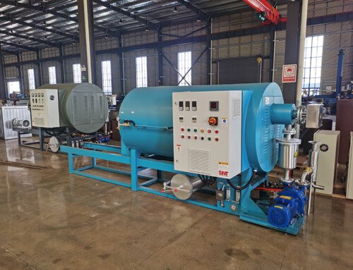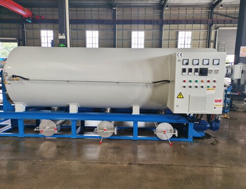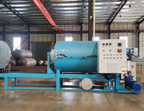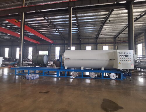
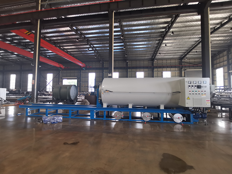
Addressing deformation in a screw cleaning furnace’s inner chamber is a critical maintenance task that directly impacts cleaning efficiency, process consistency, and operational safety. This type of furnace is specifically designed for the thorough removal of carbon deposits and polymer residues from plastic processing screws and tooling. Chamber deformation, often a gradual process, can lead to uneven heating, compromised vacuum integrity, and potential damage to expensive tooling, making timely identification and correction essential for restoring optimal performance.
Identifying deformation causes and early symptoms
Effective troubleshooting begins with understanding the root causes and recognizing the early warning signs of chamber distortion before it leads to a major failure.
The most common cause of deformation is thermal stress from uneven heating or rapid thermal cycling. If heating elements fail or their control loops become unbalanced, one section of the chamber may heat or cool faster than another. This creates internal stresses that can warp the chamber walls over time. Similarly, operating the furnace above its designed maximum temperature for extended periods can weaken the chamber material, making it susceptible to creep and deformation under its own weight or from minor physical impacts.
Mechanical stress is another significant factor. Overloading the furnace basket with excessive weight, or impact from mishandled tooling during loading and unloading, can dent or distort the chamber liner. This is especially true for furnaces with thin-walled inner liners designed for lightweight thermal efficiency. Another subtle cause is the failure of internal support structures, such as cracked or sagging hearth rails or damaged brickwork in ceramic-lined chambers, which no longer provide uniform support.
Operators can spot early signs through routine observation. Visual clues include difficulty in smoothly closing and latching the furnace door, which may indicate the door frame is no longer square with the chamber opening. During operation, new and inconsistent hot spots on the outer furnace casing, detected via thermal imaging, can point to internal insulation collapse or chamber wall distortion creating air gaps. A sudden increase in pump-down time to achieve vacuum or an inability to hold a stable vacuum indicates potential sealing surface warpage around door gaskets or thermocouple ports.
Step-by-step assessment and measurement procedures
Once deformation is suspected, a structured assessment is necessary to determine its extent and plan the appropriate corrective action.
The first step is a thorough visual and tactile inspection during a complete cool-down. With the furnace cold and powered off, carefully inspect the interior chamber surface. Run a hand along the walls, feeling for any bulges, dips, or irregularities. Use a bright work light to look for reflections that appear wavy, indicating surface distortion. Pay close attention to weld seams, as these are common points for stress-induced cracking that can lead to localized deformation.
Next, perform dimensional checks. Using a straightedge and feeler gauges, check the flatness of the chamber floor and the squareness of the corners. For cylindrical chambers, use a set of inside calipers or a telescoping gauge to measure the diameter at multiple points along the height and circumference, comparing the readings to the manufacturer’s original specifications. Document all measurements with photos for comparison during future inspections.
Finally, conduct a functional test. Install a new, high-temperature door gasket and perform a vacuum leak test. If the furnace struggles to reach its base pressure or the vacuum level decays rapidly after the pump is isolated, it strongly suggests the sealing surfaces are no longer parallel, confirming chamber distortion. Monitoring the furnace’s temperature uniformity with a multi-point thermocouple array during a controlled heat cycle can also map out hot and cold zones caused by a warped chamber altering the heat reflection and radiation patterns.
Corrective strategies and implementation
The chosen repair method depends on the severity of the deformation, the chamber material, and the required precision of the cleaning process.
For minor, localized deformations such as small dents or bulges, a cold mechanical correction might be possible. This involves using specialized hydraulic rams or jacks with protective pads to gently push the deformed area back into alignment. This is a delicate operation that requires constant measurement to avoid over-correction and should only be attempted on robust, ductile metals. Following correction, the area must be polished smooth to prevent residue buildup and inspected for micro-cracks.
In cases of widespread warping or distortion affecting sealing surfaces, machining or re-surfacing is often the most reliable solution. This requires removing the inner chamber or liner and taking it to a machine shop equipped with large milling or boring equipment. The sealing flange surfaces and critical interior datum points are skimmed to restore flatness and parallelism. This process precisely removes material, so it’s crucial to verify that the remaining wall thickness still meets the design’s safety and thermal specifications.
For severe deformation, particularly in alloy steel or Inconel chambers that have undergone significant microstructural change due to overheating, replacement is frequently the only viable long-term solution. Attempting to repair a severely compromised chamber often leads to recurring problems and potential safety risks. When replacing, consider upgrading to a chamber constructed from a more thermally stable material or with improved internal bracing to prevent recurrence under your specific operating conditions.
Preventive maintenance to avoid recurrence
After resolving a deformation issue, implementing a robust preventive maintenance program is key to ensuring long-term chamber integrity.
Establish a strict thermal protocol. Always follow the manufacturer’s recommended heating and cooling rates. Avoid rapid quenching of the chamber after a high-temperature cycle. Implement a controller calibration schedule to ensure all heating zones are balanced and no single zone is over-firing, which creates localized hot spots that accelerate thermal fatigue.
Institute mechanical handling discipline. Enforce clear load limits for the furnace basket. Use dedicated, padded carts or racks for transporting tooling to and from the furnace to prevent accidental impacts against the chamber liner during loading. Train all personnel on proper loading techniques to ensure weight is distributed evenly.
Finally, formalize a regular inspection routine. Schedule quarterly internal inspections using the measurement techniques outlined above, documenting results to track any slow changes over time. Incorporate an annual vacuum integrity test and a temperature uniformity survey as part of the preventive maintenance plan. This proactive approach allows for early intervention, turning a potential catastrophic failure into a minor, scheduled maintenance item.