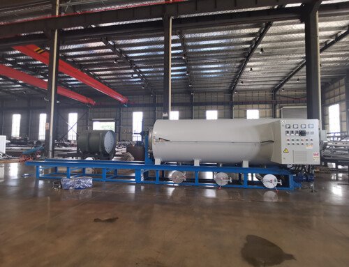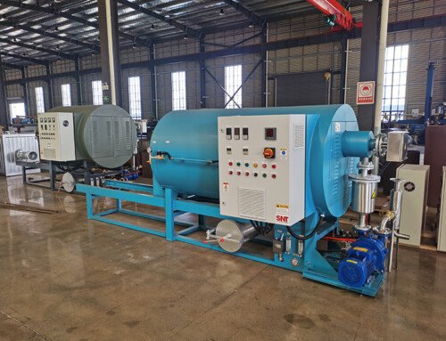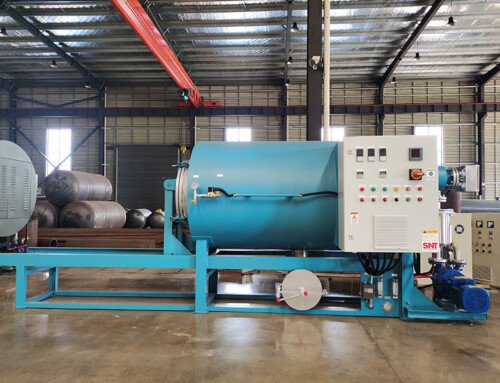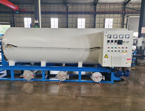
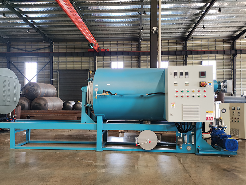
Stable floor load distribution forms the quiet foundation of long-term, trouble-free operation for a screw cleaning furnace, even when many installation teams treat this factor as an afterthought. Uneven or underestimated floor loading can trigger slow, subtle shifts in equipment alignment over months of operation, creating cascading problems that range from minor vibration during heating cycles to premature wear on precision internal components. These issues often develop gradually, making them easy to misdiagnose as routine mechanical wear rather than a root problem tied to improper load planning during the placement phase. Taking the time to map out load distribution carefully before positioning the unit prevents dozens of avoidable operational headaches down the line.
Static and dynamic load distribution mapping
The total weight of a fully assembled screw cleaning furnace, when combined with the maximum weight of all internal process loads and circulating high-temperature media, creates concentrated load points at every support foot on the unit’s base. These individual point loads must be carefully mapped across the floor area to ensure no single support transfers more weight than the underlying floor structure is rated to handle. Dynamic loads that come from normal operational vibration, thermal expansion shifts, and occasional service activities add additional temporary stress that static load calculations alone do not fully capture. Spreading these concentrated points across a wider, reinforced base plate distributes force more evenly and eliminates localized stress spikes that could otherwise cause floor surface deformation over extended operating periods.
Floor flatness and settlement allowance
Even a perfectly level floor at the time of installation can experience minor differential settlement over years of heavy industrial use, especially under the sustained weight of a high-temperature processing unit. Small deviations in flatness that are too slight to notice during initial setup can create subtle twisting stress across the furnace frame, pulling mounting points out of parallel and interfering with the smooth travel of internal moving components. Pre-installation floor leveling checks across the entire footprint, paired with adjustable shim packs at every support point, give technicians the ability to correct minor deviations and maintain precise frame alignment long after the initial placement. This proactive adjustment capacity compensates for slow, natural floor movement before it can distort the unit’s critical internal clearances.
Proximity to high-traffic load zones
Areas of the factory floor that regularly see heavy forklift traffic, rolling cart movement, or frequent heavy equipment repositioning experience far higher concentrated impact loads than static floor ratings alone might suggest. Placing a screw cleaning furnace too close to these high-traffic zones exposes its supporting floor area to repeated sudden impact stress that can create unexpected micro-cracks in floor slabs or shift alignment over time. Creating a clear buffer zone around the unit’s footprint keeps all heavy moving equipment far enough away that their dynamic load spikes do not transmit vibration or force into the furnace’s stable resting position. This separation also eliminates the risk of accidental vehicle collision with the unit’s base frame, which could jolt critical internal components out of precise alignment.
Thermal expansion and floor surface interaction
When the furnace reaches full operating temperature, its metal base frame will experience predictable thermal expansion that shifts the position of support feet slightly outward across the floor surface. If the base is locked in place with fully rigid anchors that do not accommodate this small natural movement, internal stress can build up in the frame and transfer upward to warp precision internal guide surfaces. Leaving controlled, low-friction clearance at each support point allows the frame to expand and contract freely with temperature cycles without creating binding stress against the floor. This small detail prevents hidden mechanical tension from building up in the equipment structure, which would otherwise lead to unexpected performance drift after repeated heating and cooling cycles.