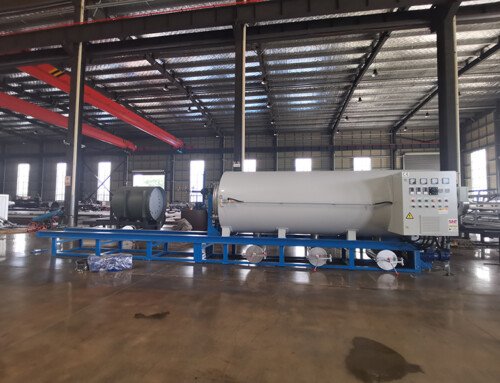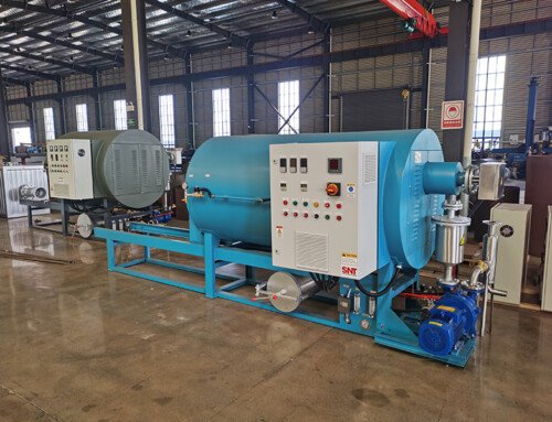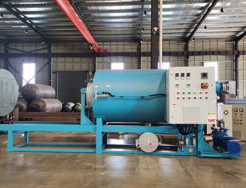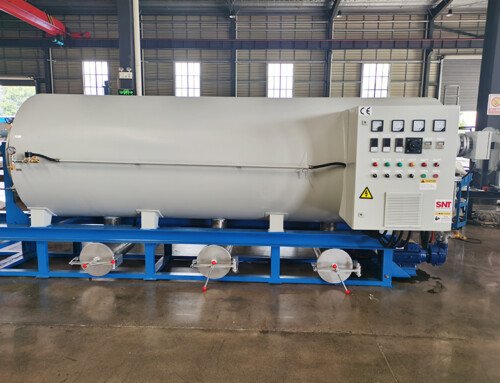
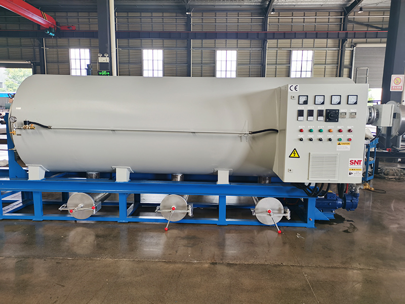
Proper shock protection during the installation phase directly affects long-term operational stability, thermal uniformity, and overall equipment lifespan. Even minor unaddressed vibration can gradually loosen internal fasteners, shift heating element alignment, and introduce unnecessary stress on precision components. The following practical installation techniques focus on structural alignment, load distribution, and dynamic vibration control to keep the unit running reliably under typical industrial floor conditions.
Pre-installation site assessment for vibration sources
Before placing any mounting hardware, map out all nearby equipment that generates continuous or periodic vibration. This includes nearby rotating machinery, stamping presses, conveyor systems, and even heavy vehicle traffic on adjacent roadways. Document the approximate operating frequency and peak vibration amplitude across different time windows, so you can design a protection scheme that targets the actual disturbance profile rather than applying a generic setup.
Mark the exact footprint of the unit on the floor and extend that assessment outward by at least one meter in all directions. Check for floor joints, expansion gaps, or structural weak points that could amplify transmitted motion. Avoid positioning the installation point directly above building expansion joints or near columns that carry concentrated dynamic loads from upper floors.
Leveling and load distribution before final fastening
Clean the entire installation surface thoroughly to remove grease, loose concrete particles, and residual welding debris. Use a precision spirit level to verify flatness across the full base area, and correct any uneven spots that exceed 2 mm per meter. Even small deviations can cause uneven compression on shock-absorbing elements and create unintended tilt during later thermal cycles.
Arrange all support points symmetrically around the equipment’s center of gravity, rather than simply placing them at the four outer corners. This layout ensures that static weight and dynamic operational forces spread evenly across every contact point. After initial placement, press down gently on each corner of the frame and confirm that no single support point carries a disproportionate share of the total load.
Vibration isolation element alignment and preload adjustment
Position each isolation component carefully so its central axis lines up vertically with the corresponding mounting point on the equipment base. Avoid angled installation, which can introduce lateral shear forces that degrade isolation performance over time. Once all elements are in place, lower the equipment frame slowly and make sure no part of the base makes direct rigid contact with the floor.
Adjust each support point incrementally and in a crisscross sequence, rather than tightening one side fully before moving to the next. This method prevents unintended frame twist and keeps the entire structure balanced. After adjustment, confirm that every isolation element shows consistent compression height, indicating that each one is carrying its designed share of the load without being overstressed.
Post-installation dynamic check and initial operation verification
Once all fasteners are secured with the correct torque sequence, perform a manual push test in both horizontal directions to confirm the structure moves smoothly and returns to a neutral position without sticking or excessive wobble. Any binding or uneven resistance usually signals misalignment or an improperly adjusted isolation point that needs rework before powering on the system.
Run the equipment through a short, low-temperature test cycle and monitor vibration levels at multiple points on the frame and floor. Pay special attention to startup and shutdown phases, where transient forces are most likely to reveal resonance issues. If you notice sudden vibration spikes at specific operating states, readjust the preload on individual supports to shift the system’s natural frequency away from that disturbance range.
Ongoing structural inspection after installation
Set a regular interval to check all connection points for loosening, especially after the unit has gone through repeated heating and cooling cycles. Thermal expansion and contraction can gradually alter preload values, so periodic re-verification of support compression helps maintain consistent isolation performance. Inspect all flexible components for signs of aging, surface cracking, or permanent deformation that could reduce their ability to absorb vibration over extended use.
Keep a simple log of vibration readings taken at the same operating conditions every few months. This trend record makes it much easier to spot slow performance degradation long before it develops into a noticeable operational problem. Small adjustments made early in the maintenance cycle can prevent major structural misalignment and preserve the stable thermal environment the process requires.