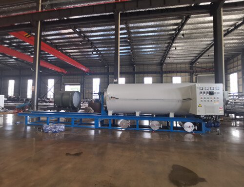
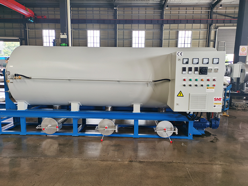
Screw cleaning oven power supply location installation planning
Careful power supply location installation planning for a screw cleaning oven prevents long-term electrical wear, unplanned mid-cycle shutdowns, and hidden operational hazards that can develop over thousands of heating cycles. Unlike standard low-draw workshop equipment, these units generate sustained high ambient heat around their outer shell and draw a stable, heavy electrical load during long cleaning runs. A poorly positioned power setup will degrade cable insulation over time, create unprotected trip hazards, or leave operators without quick access to emergency shutoff points. A properly planned layout aligns every electrical component with the oven’s thermal footprint, daily workflow patterns, and maintenance access requirements to deliver consistent, safe performance across years of regular use.
Pre-installation thermal and workflow hazard mapping
Before any wiring is run, teams conduct a full on-site walkthrough to document every condition that could impact power system safety and reliability. They map the full heat radiation zone around the oven’s outer shell, marking all areas where surface temperatures stay elevated for extended periods after a full cleaning cycle. No power outlet, disconnect switch, or exposed cabling segment can fall within this high-temperature band, because sustained heat exposure will break down cable insulation gradually and create hidden fault risks that are nearly impossible to spot during casual routine checks.
Teams also trace the full daily workflow path around the equipment, including routes used to carry heavy screw assemblies in and out of the oven, paths for moving cleaning tools and spare parts, and zones where material carts and mobile work platforms regularly pass through. No power hardware or loose cabling is placed in these high-traffic zones, where accidental impact from moving loads could yank connections loose, crack outlet housings, or tear cable insulation.
Existing site electrical infrastructure is reviewed in detail during this phase. Teams confirm the dedicated circuit for the oven shares no load with other high-draw thermal equipment, and that the planned power location sits within a short, direct wiring path from the circuit breaker panel. This eliminates the need for long, unprotected cable runs stretched across open floor space, which are one of the most common sources of workshop electrical accidents.
Power hardware mounting and access optimization
Once the hazard map is finalized, teams select the exact mounting positions for the main emergency disconnect and the oven’s equipment-side power inlet. The emergency disconnect switch is mounted on a stable adjacent wall, at a height that lets any operator reach it with one natural, unobstructed motion, no step stool or awkward stretching required. This placement ensures personnel can cut power to the full unit in seconds during any unexpected operational anomaly, without fumbling around the back of the machine or searching through cluttered work zones for a hidden shutoff point.
The equipment-side power inlet is fixed to the oven’s non-operating face, completely away from the main loading door and the standing position operators use to load and unload screw parts. This placement keeps the power cable and connection point far from the bursts of hot air that escape every time the oven door is opened, and prevents accidental contact with live electrical components during routine material handling. The short, straight cable between the inlet and wall-mounted disconnect is secured inside a rigid protective channel along the wall or floor, with no loose hanging segments that could create trip hazards.
A clear, unobstructed buffer zone is reserved around the entire power assembly. No storage bins, cleaning supplies, or spare screw components are stacked inside this zone, so maintenance technicians can reach every connection point during periodic inspections without moving heavy obstructions out of the way. This uncluttered access cuts down troubleshooting time significantly, and prevents accidental impact damage to power hardware from stacked stored items.
Thermal protection and post-installation functional validation
After all power hardware is wired and secured, teams add targeted safeguards to protect the circuit from the unique operating conditions around a screw cleaning oven. Every wiring segment that runs near the oven’s heat radiation zone uses high-temperature rated cabling, with no standard general-purpose wiring exposed to sustained elevated ambient temperatures. All terminal connections inside junction boxes are tightened to the specified torque value, to eliminate loose points that could generate excess heat under the unit’s full operating load.
Teams also make sure no ventilation openings on power supply hardware face directly toward the oven’s exhaust vent. This prevents fine particulate and residual volatile fumes released during the cleaning cycle from drifting directly into electrical components, where they could build up over months of operation and cause gradual insulation contamination. This small, often overlooked detail prevents hidden electrical faults that would otherwise only appear after hundreds of operating cycles.
The final validation process runs the oven through multiple full heat-up and cool-down cycles, with technicians monitoring voltage stability at the equipment inlet under maximum draw. They test the emergency disconnect repeatedly to confirm it trips reliably every time, and walk through every standard operator workflow to confirm no part of the power layout creates an unexpected obstruction or safety risk. All test readings are logged and stored in the equipment’s maintenance record, so future inspection teams can compare new data against the original baseline to spot subtle drift before it develops into a serious operational issue.