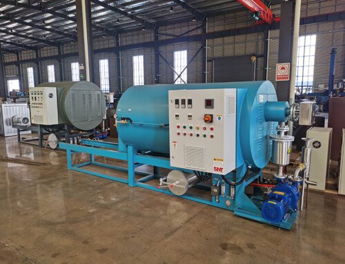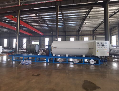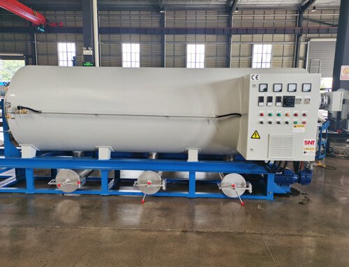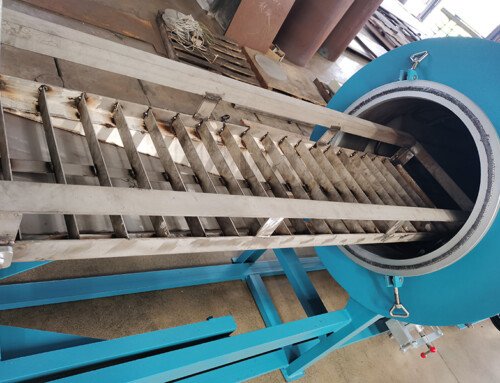
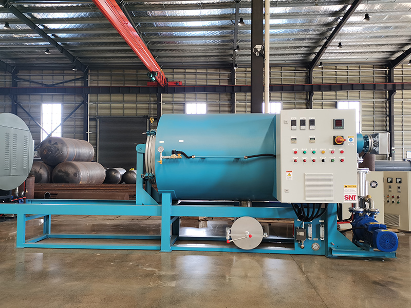
Proper ventilation and heat dissipation setup is one of the most critical steps to maintain stable long-term operation for industrial thermal processing equipment. Without a well-designed airflow layout, excess radiant heat can accumulate around internal components, shorten service life, and create unnecessary safety risks during extended production cycles. Every installation decision should start with a clear understanding of the surrounding site conditions, rather than relying on generic setup guidelines that do not match actual workshop constraints.
Site Survey and Clearance Planning
Before any ductwork or vent opening is cut, walk through the entire installation zone to map out existing heat sources, exhaust routes, and nearby sensitive equipment. Confirm that the wall or roof openings reserved for ventilation do not face prevailing seasonal winds that could push exhaust fumes back into the workspace. Maintain consistent clearance between the furnace outer shell and surrounding walls, structural beams, or stored materials, so natural convective air can flow freely along all exterior surfaces without being blocked.
Check the ambient air quality in the proposed location to make sure no corrosive aerosols, heavy dust particles, or solvent vapors are continuously drawn into the cooling airflow. These contaminants can gradually coat internal heat exchangers, reduce thermal transfer efficiency, and create uneven hot spots that become hard to resolve later. Document all measured distances, nearby obstructions, and seasonal weather patterns that might affect airflow direction before finalizing any installation drawing.
Airflow Path Design and Duct Layout
Design the main exhaust path to follow the natural rising direction of hot air, so heated air does not get trapped in sharp bends or extended horizontal duct runs. Keep straight duct segments as smooth and short as possible, and minimize unnecessary elbows that create backpressure and slow down exhaust velocity. If a long duct run is unavoidable, add intermediate access openings at regular intervals to support future inspection and cleaning without full disassembly.
Position fresh air intake points at lower elevations relative to the furnace, so cool ambient air can be drawn in naturally to replace the hot air being expelled. Avoid placing intake openings near equipment that generates its own waste heat, because pre-heated incoming air will reduce the overall cooling effect and force internal components to run at higher operating temperatures. All joint connections along the duct should be sealed securely to prevent unplanned air leakage that disrupts the designed airflow balance.
Safety Interlock and Overheat Protection Integration
Connect all ventilation system safety switches to the main equipment control circuit, so the heating cycle cannot start if the primary exhaust fan fails to reach its normal operating speed. This prevents the furnace from building up excessive internal temperature when airflow is insufficient, and stops heat from spilling out into the surrounding cabinet space. Install independent temperature sensors along critical heat dissipation surfaces, so the system can trigger an early warning before surface temperatures rise beyond preset safe thresholds.
Test every interlock function individually during initial commissioning, simulating fan failure, blocked vent conditions, and unexpected power interruptions to confirm the protection logic responds as intended. Never bypass these safety features to force production to resume, even if temporary operational pressure makes that seem like a quick solution. Regularly verify that all sensor readings remain accurate, because drift over time can create blind spots where overheating develops without any visible alert.
Post-Installation Airflow Verification
Once all mechanical connections are complete, run the ventilation system alone for a full test cycle before activating any heating elements. Use an anemometer to measure airflow speed at every key intake and exhaust point, and compare the recorded values against the design targets to identify unexpected restrictions. Watch for areas where airflow appears turbulent or recirculating, and adjust baffle positions slightly to smooth out the flow pattern.
After the first full heat cycle, walk around the entire outer structure and check for uneven surface temperatures that signal trapped heat or poor local cooling. Mark any locations that show abnormal heat buildup, and adjust nearby vent openings or add supplementary local airflow guidance to resolve the issue. Keep a log of all measured airflow values and temperature readings, so future routine inspections can quickly spot any gradual performance drop that develops over months of continuous operation.