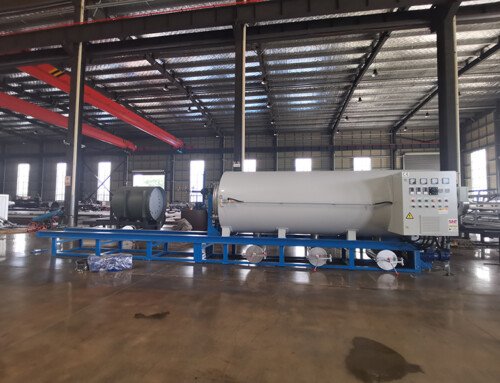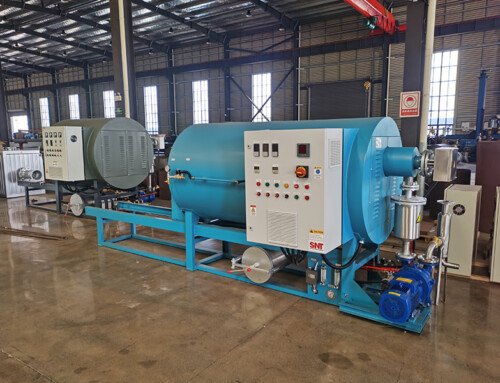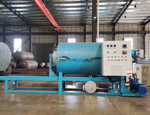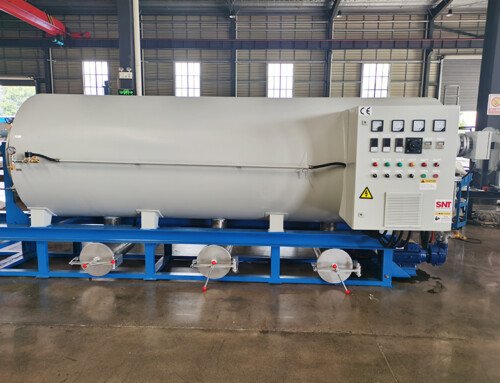
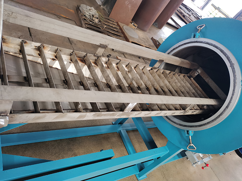
Proper circuit wiring for screw cleaning furnaces forms the foundation of long-term operational safety and consistent thermal performance. Every connection point inside the furnace cabinet interacts with high-temperature cycling, dust accumulation, and occasional thermal expansion stress, which means even minor wiring oversights can lead to unplanned shutdowns or gradual component degradation. All installation steps must follow standardized electrical safety frameworks and align with site-specific environmental conditions to ensure stable power delivery across every operational phase.
Pre-installation safety checks and tool preparation
Before any wiring work begins, confirm the entire upstream power supply is fully disconnected and verified with a calibrated voltage testing device to eliminate residual electrical risk. Prepare insulated hand tools, precision wire strippers, crimping tools, high-temperature resistant insulating wraps, and heat shrink tubing rated for the maximum operating temperature of the furnace’s surrounding area. Inspect all incoming wiring for visible insulation damage, and confirm each conductor’s cross-sectional area matches the calculated current load for the furnace’s heating elements and control modules. Clear the installation zone of loose metal shavings, leftover furnace insulation debris, and any flammable materials that could be disturbed during the wiring process.
Conductor stripping and terminal connection best practices
Strip the outer insulation layer to a precise length that matches the depth of the corresponding terminal port, typically between 10 and 12 millimeters for standard power connections. Avoid scratching or nicking the internal copper strands during stripping, as damaged conductors will reduce effective current carrying capacity and create localized hot spots under full load. For multi-strand flexible wires, twist the exposed copper strands gently in a clockwise direction to prevent loose strands from protruding outside the terminal housing after insertion. When inserting conductors into screw-type terminals, align the wire loop in the same clockwise direction as the tightening screw, so the conductor pulls tighter instead of slipping out as torque is applied. Never leave exposed copper outside the terminal body, and never trap any section of the outer insulation inside the terminal port, as both conditions lead to poor contact or unintended electrical exposure.
High-temperature zone wiring routing and protection
Route all power and signal wiring away from direct contact with the furnace’s outer heating jacket and exhaust duct surfaces. Maintain a minimum clearance distance that accounts for maximum thermal expansion of both the furnace structure and the wiring itself. Use high-temperature rated wire looms or ceramic wire guides to secure conductors that pass through areas with sustained elevated ambient temperatures, preventing insulation brittleness over repeated heating cycles. Separate high-power heating element wiring from low-voltage sensor signal wiring by a physical gap of no less than 20 centimeters, to minimize electromagnetic interference that could distort temperature reading accuracy. Add strain relief clamps at every entry point into the control cabinet and furnace body, so vibration from nearby equipment or regular maintenance movement does not pull connections loose over time.
Insulation verification and post-installation functional testing
After all wiring connections are secured, perform a full insulation resistance test between each conductor and the grounded metal chassis, ensuring readings meet the minimum safety threshold for industrial electrical installations. Wrap every exposed joint and terminal transition point with overlapping layers of high-temperature insulating wrap, then slide heat shrink tubing over the wrapped section and apply uniform heat to create a sealed, dust-resistant barrier. Double check all ground path connections to confirm continuous, low-resistance bonding across every metal section of the furnace frame and control enclosure. Restore power gradually through a step-up sequence, first activating low-voltage control circuits to verify sensor readings and interlock logic, then energizing heating elements in staged groups to monitor for abnormal current draw or localized overheating at connection points.