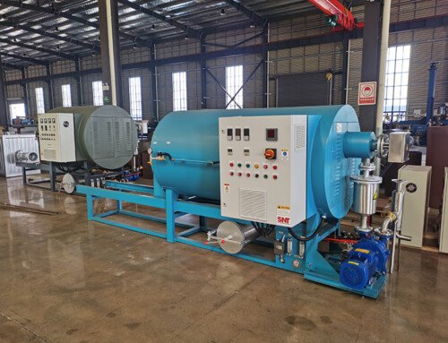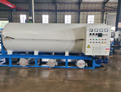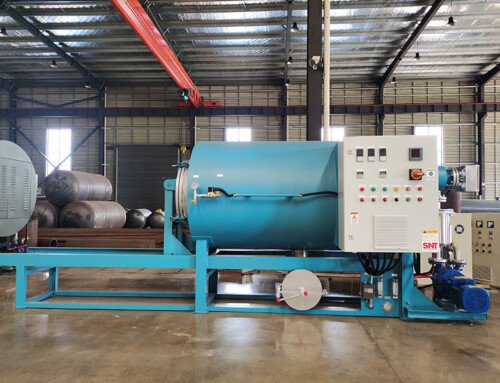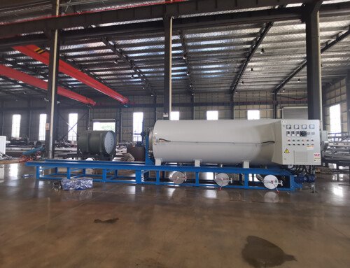
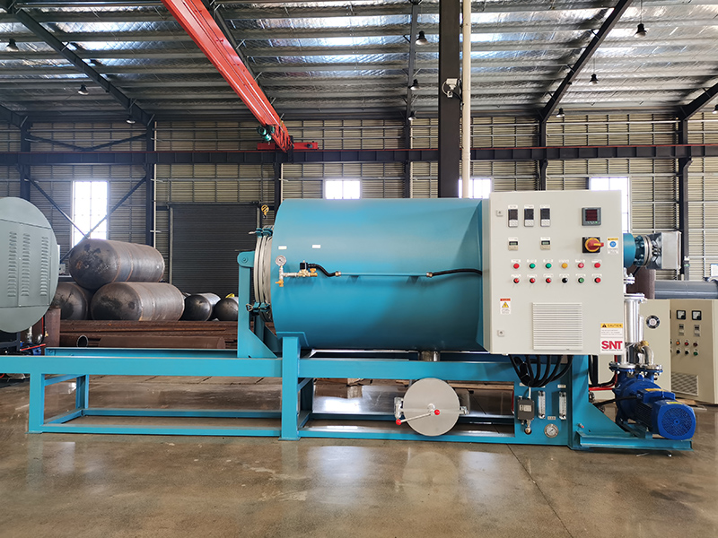
The installation foundation for a screw cleaning furnace is a critical structural element that directly influences the long-term stability, operational safety, and performance efficiency of the equipment. A properly designed and constructed base absorbs operational vibrations, prevents settling and misalignment, and provides a level, secure platform that supports the furnace’s weight and dynamic loads throughout its service life. Adhering to precise foundation requirements mitigates risks of premature wear, mechanical failure, and costly post-installation corrections.
Site Assessment and Preliminary Planning
Before any concrete is poured, a thorough site assessment must be conducted. The chosen location within the plant must offer sufficient space not only for the furnace’s footprint but also for operational access, maintenance activities, and potential future service needs. The underlying soil’s bearing capacity must be professionally evaluated to ensure it can support the concentrated load of the furnace and its foundation without excessive settlement. The area must be dry, well-ventilated, and free from excessive airborne contaminants that could affect the furnace’s electrical components or heat exchange efficiency. Proximity to necessary utilities—such as three-phase power, water supply for cooling, and drainage—should also be factored into the initial layout planning to minimize lengthy and inefficient connection runs.
Foundation Design Specifications and Construction
The foundation’s design must be based on the equipment manufacturer’s specific technical data, which includes the furnace’s total weight (both static and operational), footprint dimensions, and the exact locations and sizes of anchor bolt holes. Typically, a reinforced concrete mat foundation is required. The concrete mix should achieve a minimum compressive strength, often specified as C25/30 or higher, to ensure durability. The foundation’s length and width should exceed the equipment base plate by at least 150-200mm on all sides. Its depth is calculated based on load-bearing requirements and frost line considerations in colder climates. Critical to the process is the precise placement of anchor bolts or embedded plates within the formwork before pouring. These must be set to exact coordinates and held rigidly in place to prevent displacement during the concrete pour, ensuring a perfect match with the furnace’s base.
Surface Finish, Leveling, and Ancillary Features
The top surface of the finished foundation requires meticulous finishing. It must be leveled to a very high tolerance, typically within 1mm over a 1-meter span, to prevent stress on the furnace’s frame upon installation. A smooth, hard-troweled finish is necessary to provide a consistent bearing surface. It is common practice to design the foundation’s top surface to be slightly elevated above the surrounding finished floor level. This elevation, combined with a perimeter drainage channel or a gently sloped surface, facilitates the containment and channeling of any potential water spills or cleaning runoff away from the base, preventing pooling and corrosion. Furthermore, provisions for conduit runs for power cables and piping trenches for utility connections should be integrated into the foundation design or planned in the surrounding floor area to maintain a clean and safe workspace.
Curing, Preparation, and Final Installation Readiness
After pouring, the concrete foundation must cure properly for a period specified by the concrete supplier, often a minimum of 7 to 28 days, to achieve its full design strength. Rushing this process can lead to cracking and reduced load-bearing capacity. Prior to moving the furnace into position, the foundation surface must be thoroughly cleaned and inspected for any imperfections. The precise locations of the anchor bolts are verified against the equipment drawings. Once the furnace is positioned using appropriate lifting equipment, leveling is achieved using precisely machined steel shims or epoxy grout injected beneath the baseplate. Finally, the anchor bolts are torqued to the manufacturer’s specified values in a cross-pattern sequence to ensure an even and secure clamp load, completing the mechanical bond between the equipment and its foundational support.