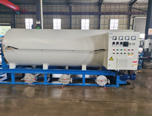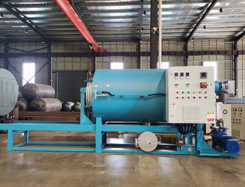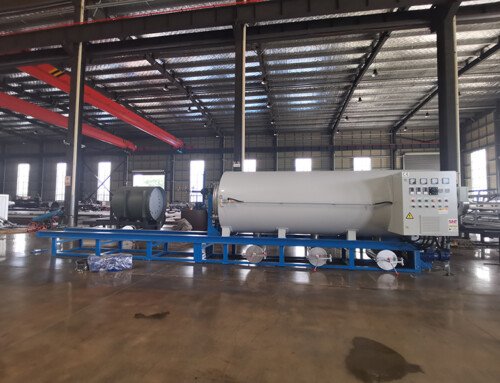
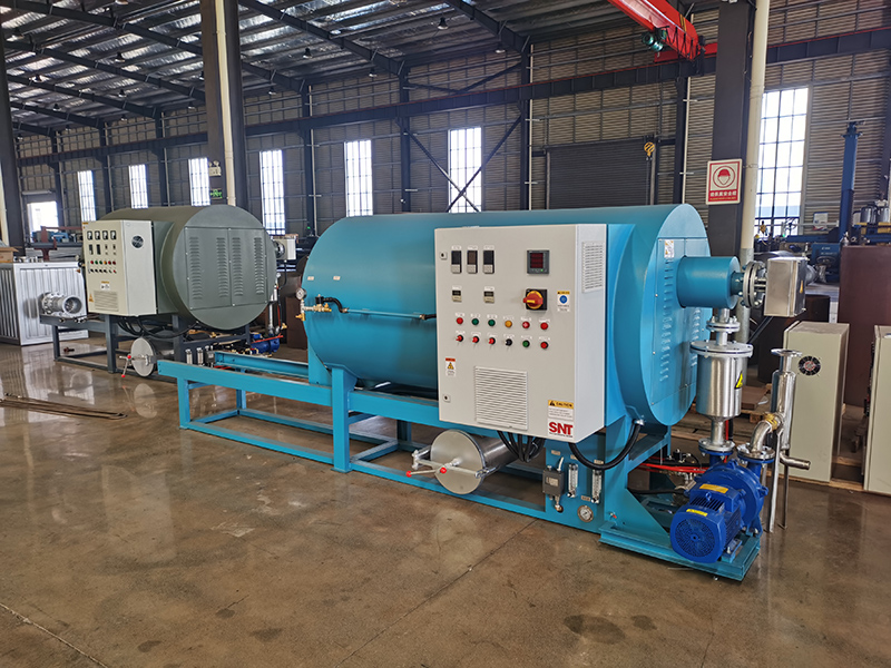
Verify Foundation Load Capacity and Thermal Expansion Clearance Before Placement
Check the installation site’s concrete foundation or support frame to ensure it can handle the full operational weight of the furnace, including the thermal mass during heating cycles. Use a spirit level across the entire base frame to confirm it is perfectly horizontal, as even a slight tilt can cause uneven stress on the screw conveyor and drive components over time. Leave sufficient clearance around the unit, particularly near the heating zones and discharge end, to accommodate thermal expansion during operation and to allow safe access for future maintenance tasks like seal replacement or screw inspection.
Align the Screw Conveyor and Drive Assembly with Precision During Mechanical Installation
During the initial mechanical assembly, focus on achieving precise concentric alignment between the screw flights and the internal barrel or tube. Use dial indicators to measure runout at multiple points along the screw’s length as it is rotated manually, making fine adjustments to the support bearings until the runout is within the manufacturer’s specified tolerance. Misalignment at this stage is a leading cause of premature wear, increased power consumption, and uneven cleaning results. Also, ensure the drive motor and gear reducer are aligned according to the coupling manufacturer’s specifications to prevent vibration and bearing failure.
Conduct a Cold Run and Leak Test Before Introducing Heat or Process Materials
With all mechanical and electrical connections complete, run the screw conveyor at its lowest speed without applying any heat. Listen for unusual noises like grinding, clicking, or irregular scraping that could indicate misalignment or obstructions. Simultaneously, perform a pressure decay test or soap bubble test on the vacuum system and any sealed compartments to verify there are no leaks at flange connections, valve stems, or sight glass seals. Addressing these issues while the system is cold and empty is far simpler and safer than trying to correct them during a hot, operational cycle.
Execute a Graduated Thermal Cycle Test to Validate Control System and Safety Interlocks
Begin the first heating test with an empty chamber. Program the controller to execute a slow, stepwise temperature ramp up to the standard operating range, holding at intermediate temperatures to allow the structure to expand evenly. Monitor the temperature readings from multiple zones against the controller setpoints to calibrate any offsets. Verify that all safety interlocks—such as over-temperature cutoffs, pressure relief valves, and screw jam sensors—activate correctly at their designated setpoints. This controlled empty run confirms that the heating, control, and safety systems are functioning as an integrated unit before any cleaning workload is introduced.
Document Baseline Performance Metrics During the Initial Operational Cycles
After successful empty tests, run the first few cleaning cycles with a known, standard load—such as a set of lightly soiled spare parts. Record key operational data: the time required to reach target temperature, stability of temperature zones, screw motor current draw, vacuum level consistency, and final cleanliness results. This establishes a performance baseline for the specific installation. Comparing future operation against this baseline makes it easier to detect gradual degradation, such as increasing heat-up times or rising motor current, which can signal developing issues like insulation wear or bearing friction.