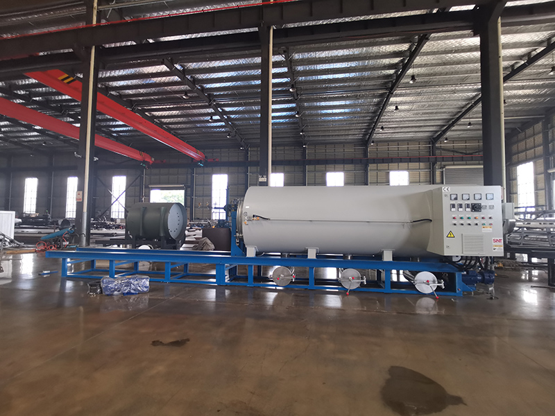
Abrnormal cooling speed in a screw cleaning furnace disrupts the thermal cycle, potentially leaving residual contaminants or affecting the readiness of cleaned components for the next process step. This issue can stem from inefficiencies in the heat removal system, changes in process parameters, or mechanical wear within the cooling circuit. Diagnosing and rectifying the problem requires a methodical investigation of the cooling medium, heat exchange surfaces, and the control logic governing the cooldown phase.
Heat Exchanger Performance and Coolant Flow Analysis
The primary suspect in slowed cooling is often the heat exchanger or the system responsible for removing heat from the circulating fluid. A thorough inspection should begin with the coolant side. Check for reduced flow rate caused by a partially closed valve, a clogged strainer or filter in the coolant line, or a failing circulation pump. Mineral scale, biological growth, or particulate fouling on the heat exchanger tubes significantly impedes heat transfer. This can be assessed by comparing the temperature differential (ΔT) across the heat exchanger with the manufacturer’s specifications under a known load; a lower-than-expected ΔT often indicates poor heat transfer efficiency. For shell-and-tube designs, internal tube blockage is a common culprit, requiring mechanical or chemical cleaning to restore full flow and surface area contact.
Circulation System Integrity and Process Load Verification
The internal circulation of the cleaning fluid within the furnace itself must be verified. Ensure the furnace’s main circulation pump is operating at full capacity and that there are no obstructions in the internal spray nozzles, manifolds, or tank outlets that would reduce fluid movement over the parts and heating elements. A worn pump impeller or cavitation can drastically reduce flow. Simultaneously, evaluate if the process load has changed. An increase in the mass or thermal capacity of the parts being cleaned (e.g., a denser batch of components) requires more energy to be removed, naturally extending the cooling time. Overloading the furnace beyond its design capacity is a frequent cause of perceived cooling slowdown.
Control System Calibration and Cooling Phase Logic
The automated control system managing the cooling cycle must be examined. A faulty or miscalibrated temperature sensor (RTD or thermocouple) can provide an inaccurate reading to the controller, causing it to believe the cooling phase is complete prematurely or to mismanage the cooling rate. Review the programmed cooling logic. Some systems use a simple timed cooldown, while others cool to a specific setpoint. Ensure the setpoints and timers are correctly configured. If the system uses modulating valves to control coolant flow based on temperature, verify that these valves are opening fully when commanded. A sticking or failed valve actuator can severely limit coolant flow, throttling the cooling rate. Checking control outputs and valve positions during an active cooling cycle is essential for identifying such control-related faults.