Troubleshooting Methods for Heating Element Failure in Screw Cleaning Ovens
Heating element failure is a critical malfunction in screw cleaning ovens that directly halts the core thermal process, preventing the oven from reaching or maintaining its required operating temperature. Effective troubleshooting moves from simple external checks to internal electrical and mechanical diagnostics, building upon the systematic approach established for related faults like startup failures or temperature instability. A methodical investigation is essential to accurately identify the root cause—whether electrical, physical, or control-related—and implement a precise corrective action.
Initial Visual and Operational Symptom Assessment
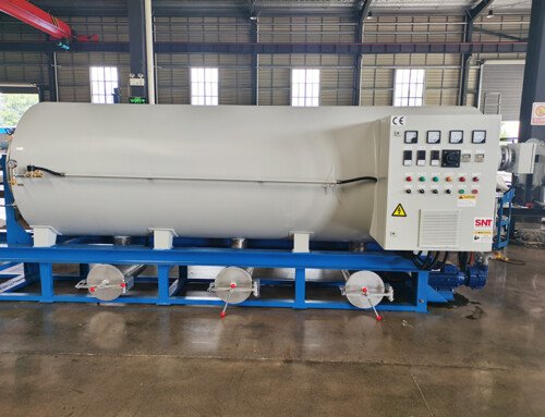
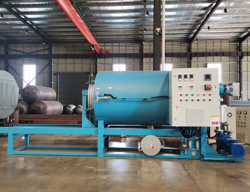
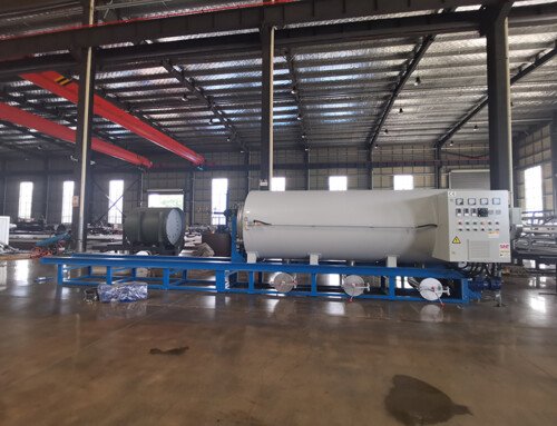
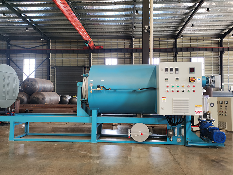
Begin with a comprehensive visual inspection of the oven chamber and the heating element housing areas, following all lockout/tagout procedures to ensure the system is de-energized and cooled. Look for obvious signs of physical damage: broken or sagging heating coils, localized discoloration (bluing or whitening) indicating extreme overheating, cracks in ceramic insulators, or signs of molten metal. Check for any foreign material or cleaning residue that may have bridged and shorted the elements. Prior to shutdown, note the operational symptoms: Is the oven failing to heat at all, or is it heating unevenly? Are there error codes on the controller related to heater open circuit, short circuit, or overcurrent? Does the ammeter for the heating circuit show zero draw (suggesting an open) or an abnormally high draw (suggesting a short or ground fault)?
Electrical Continuity, Resistance, and Insulation Testing
With power safely disconnected and locked out, perform detailed electrical testing using a multimeter. First, test for continuity across each individual heating element. A complete lack of continuity confirms an open circuit due to a broken wire within the element. Next, measure the resistance of each element and compare it to the manufacturer’s specified value (often calculated using Ohm’s Law: R = V² / P). A significantly higher resistance may indicate a partial break or poor internal connection; a significantly lower resistance suggests a short circuit between coils. Finally, and critically, perform an insulation resistance (megger) test between each element’s terminals and the grounded oven chassis. Apply a test voltage (e.g., 500VDC) as per safety standards. A reading below the minimum acceptable threshold (typically >1 MΩ) indicates a breakdown of the element’s insulation, creating a ground fault that can trip safety breakers and poses a shock hazard.
Mechanical and Environmental Causation Analysis
If electrical tests are inconclusive or point to a repeated failure pattern, investigate the mechanical and operational environment. Examine the element mounting and support hardware. Loose or corroded brackets can cause vibration and physical fatigue, leading to breakage. In ovens with cyclic cooling, repeated thermal expansion and contraction can stress element connections over time. Analyze the process conditions: Has the oven been operated consistently above its rated temperature? Has there been exposure to corrosive fumes from certain cleaning chemicals that could degrade the element sheath material (e.g., chlorides attacking certain stainless steels)? Check for improper airflow around the elements due to a failed circulation fan or blocked vents, which can cause localized overheating and burnout. Ensure that temperature sensors (thermocouples) are correctly positioned and calibrated, as a faulty sensor can cause the control system to overdrive the elements continuously.
Control Circuit and Power Supply Verification
Before concluding the heating elements are faulty, verify the integrity of the supporting control and power delivery systems. Use the multimeter to check for the presence of the correct voltage at the element terminals when the controller calls for heat (exercise extreme caution with live voltage testing). The absence of voltage points to a problem upstream, such as a failed contactor, a tripped heater relay, a blown fuse, or a fault in the Solid-State Relay (SSR) or thyristor controller. Test these components for proper operation. Also, inspect all terminal connections at the element, contactor, and control board for signs of arcing, overheating (discoloration), or looseness. A poor connection creates high resistance, leading to localized heating at the terminal that can burn out wires and damage the element terminals, even if the element coil itself is intact. This step ensures that a control system fault is not misdiagnosed as a failed heating element.