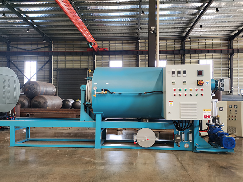
A structured maintenance routine for the cooling system of a screw cleaning furnace is essential for preventing thermal runaway, ensuring consistent processing temperatures, and protecting sensitive electronic and mechanical components from heat damage. Unlike reactive repairs after a failure, proactive upkeep maintains heat exchange efficiency and extends the operational life of the entire system.
Air-cooling component inspection and cleaning
For furnaces utilizing air-cooling, the primary maintenance focus is on airflow and heat exchanger surfaces. Weekly, inspect all cooling fins on the barrel, gearbox, or dedicated heat exchangers. Use a soft brush or low-pressure compressed air to remove accumulated dust, plastic fines, and fibrous debris that act as an insulating blanket, drastically reducing cooling efficiency. Ensure the paths for intake and exhaust air are completely unobstructed. Verify that cooling fans operate smoothly, without bearing noise or vibration, and that their guards are clean and secure. In environments with high airborne contaminants, consider inspecting and cleaning fan blades and motor housings more frequently to prevent buildup that can imbalance the fan.
Liquid cooling circuit maintenance and fluid management
Systems with liquid cooling require meticulous attention to the coolant and its pathway. Check the coolant level in the reservoir at the start of each week when the system is cold. Top up only with the manufacturer-recommended coolant type; mixing different chemistries can cause gelation or corrosion. Monthly, inspect the coolant’s condition. Discoloration, cloudiness, or the presence of particulates indicate contamination or breakdown. Test the coolant’s pH and corrosion inhibition strength periodically, as recommended by the coolant supplier. Annually, or per the service schedule, flush the entire cooling circuit. Drain the old coolant, flush with a cleaning solution if needed to remove scale or biological growth, and refill with fresh, properly mixed coolant. This prevents clogging in narrow passages and maintains optimal thermal conductivity.
Pump, valve, and hose integrity verification
The heart of any liquid cooling system is its pump. Listen for unusual noises like cavitation (a sound like gravel flowing) or bearing whine. Feel the pump housing for excessive vibration. Ensure the pump’s strainer or filter is clean; a clogged strainer starves the pump, leading to failure and reduced flow. Inspect all coolant hoses for signs of wear, cracking, bulging, or softening. Pay special attention to areas near clamps and where hoses contact hot surfaces. Tighten hose clamps to prevent leaks but avoid over-tightening which can cut into the hose. Manually exercise any flow control or bypass valves to ensure they operate freely and can be fully opened or closed as needed. Stuck valves can divert flow away from critical cooling points.
Performance monitoring through temperature differentials
The most effective way to gauge cooling system health is by monitoring performance data. Establish a baseline for the normal temperature difference (Delta T) between the coolant inlet and outlet at standard operating loads. A decreasing Delta T over time can indicate reduced flow (from a failing pump or clog), while an increasing Delta T might point to reduced heat transfer efficiency (from fouled heat exchanger surfaces). Log the operating pressures in the cooling loop if gauges are installed; a gradual increase in pressure often signals a blockage or restriction somewhere in the circuit. Regularly compare the actual barrel temperatures in various zones to their setpoints; if certain zones begin to run hotter despite stable heater output, it may indicate localized cooling channel blockage or a loss of coolant flow in that section. This data-driven approach allows for maintenance to be scheduled based on actual performance degradation rather than just time intervals.