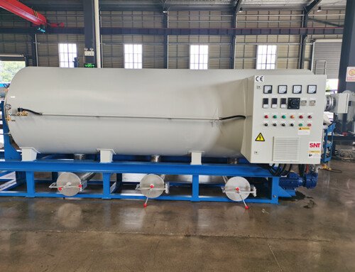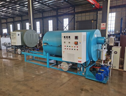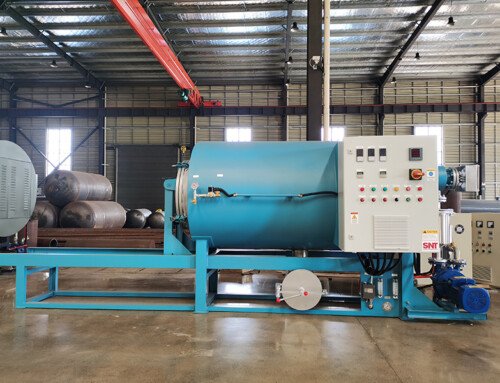
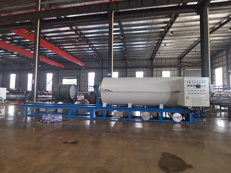
24 hour continuous batch operation of a burn off oven demands far more than simply locking the system into a non-stop heating cycle, as unplanned mid-cycle faults, uneven heat distribution, and unmanaged residual buildup can trigger unplanned shutdowns, inconsistent processing results, or even safety risks that break production flow for hours. Unlike short run batch cycles that can be fully reset, inspected, and adjusted between every load, non-stop multi-day operation requires a system architecture that balances steady thermal performance, continuous atmosphere control, and incremental maintenance that can run in parallel with production. This level of optimized operation eliminates the frequent start-stop cycles that waste energy, introduce thermal stress to chamber components, and create inconsistent processing outcomes across consecutive batches.
Seamless Batch Transition and Load Handover Design
The single biggest vulnerability in 24 hour continuous operation is the gap between finishing one fully processed batch and loading the next fresh batch, where unoptimized workflows can introduce massive temperature drops, oxygen spikes, and unplanned downtime that breaks the continuous production rhythm.
Dual Locking Airlock Load and Unload Station
Instead of opening the main processing chamber directly to ambient factory air every time a batch is swapped out, a dedicated intermediate airlock chamber acts as a buffer zone between the high temperature processing cavity and the outside environment. Operators unload finished parts and load new raw material inside this isolated airlock, where a short independent purge cycle flushes all ambient air out before the inner door to the main processing chamber is opened. This design prevents large volumes of fresh oxygen from rushing into the hot main chamber during every batch swap, eliminates massive temperature drops that would force the system to spend extra hours reheating back to operating temperature, and stops unprocessed volatile fumes from escaping directly into the surrounding work area.
Staggered Pre-Heating and Load Sequencing
While one batch is running through its full processing cycle inside the main chamber, the next incoming batch is staged inside the airlock station for low temperature pre-heating. This step evaporates all surface moisture and light low-boiling-point volatiles out of the new load before it ever enters the main hot zone, so there is no sudden surge of water vapor or light fumes that would disrupt the carefully stabilized atmosphere and temperature conditions inside the main chamber. This staggered sequencing cuts the total batch transition time down to a tiny fraction of what would be required for a full cold load start, letting the system maintain steady, uninterrupted processing output 24 hours a day.
Thermal Stability and 24/7 Heat Distribution Management
Sustained non-stop operation puts far more thermal stress on chamber walls, heating elements, and insulation layers than intermittent short run cycles, and without careful management, localized hot spots and uneven temperature drift will start to appear after 12 to 18 hours of continuous runtime.
Zoned Thermal Load Balancing Across Chamber Sections
Instead of running all heating elements at a single uniform output level for the entire multi-day run, independent temperature control zones across the chamber walls, floor, and ceiling continuously adjust their power output in real time to compensate for heat lost during batch transitions, heat absorbed by cold incoming loads, and minor natural heat drift across different sections of the insulation. This keeps the entire processing volume within a very narrow, tightly controlled temperature band across every hour of continuous operation, so parts in the far back corner of the chamber receive exactly the same thermal processing as parts positioned right next to the main heating elements. No single zone is ever forced to run at 100 percent maximum output for hours on end, which drastically extends the operational lifespan of heating components and prevents unexpected mid-cycle element failures.
Recirculating Flue Gas Heat Recovery Loop
Hot exhaust gas pulled out of the processing chamber is routed through a sealed heat exchanger that transfers a large portion of its residual thermal energy back into the incoming fresh process air and pre-heat staging area. This recovered heat is not wasted out the exhaust stack, and it reduces the total thermal load the main heating elements need to deliver to maintain stable operating temperatures. Over extended 24 hour runs, this loop also eliminates the constant cycling of heating elements between full power and idle, which reduces thermal fatigue on all high temperature components and creates a far more consistent, uniform thermal environment inside the main chamber.
Incremental In-Situ Maintenance and Long Run Fault Mitigation
Even with the best process design, small amounts of residual char, condensed tar, and particulate buildup will accumulate inside the chamber and exhaust pathways over hours of continuous batch processing, and these deposits can gradually reduce system performance or create unexpected fault conditions if left unaddressed.
Scheduled Short Intermediate Self-Cleaning Cycles
Between every 4 to 6 consecutive batches, during the short window where no new load is immediately entering the chamber, the system automatically runs a 15 to 20 minute controlled high temperature purge cycle under slightly elevated oxygen levels. This brief, controlled cycle burns off the thin layer of light char and tar residue that has built up on chamber walls, heating elements, and internal sensor surfaces, before that residue can harden into a thick, stubborn carbon layer that would insulate heating elements and block sensor readings. This incremental in-situ cleaning runs without requiring a full system cool down, and prevents the slow, gradual performance drift that would otherwise force a full unplanned shutdown halfway through a multi-day production run.
Redundant Real Time Sensor and Component Health Monitoring
Every critical sensor, heating element, and flow control valve inside the system has a paired redundant backup that runs in passive monitoring mode during normal operation. If the primary sensor starts to drift out of calibration or a heating element develops a minor performance fault, the system automatically switches over to the backup component, logs the exact fault location, and sends a notification to on-duty maintenance staff to perform a quick swap during the next scheduled batch transition window. This eliminates the situation where a single unmonitored component failure triggers a full unexpected system shutdown, letting the oven keep running continuously without breaking the 24 hour production workflow. All health data is logged over the full course of the run, so maintenance teams can identify minor degrading components long before they develop into full failures that disrupt operation.